I still have an APC Back-UPS CS500 which protects my Synology, Rasperry PI and co. Since it’s not network-capable and only has “Simple Signalling”, I want to do this with an ESP8266 smart.
I didn’t want to tinker with the UPS circuit because of the main voltage, I use the “Simple Signalling” interface to achieve the goal. The “Simple Signalling” interface is not a USB or RS232 interface!
Pin Assignment “Simple Signalling” Interface
Since I had no RJ50 plug, but a RJ48 plugs fit also, I used an old network cable for the connection, this also fits into the RJ50 socket, but then pin 1 and 10 are not usable.
| RJ50 | RJ48 | |
|---|---|---|
| 1 | +5V (10 mA) | - |
| 2 | Signal On Battery or Line Fail: Low = Line Fail, High (Ubat) = On Battery | 1 |
| 3 | Signal Low Battery: Low = Battery full, High (Ubat) = Battery empty | 2 |
| 4 | CHASGND (Schiermung) | 3 |
| 5 | not connected | 4 |
| 6 | not connected | 5 |
| 7 | GND | 6 |
| 8 | Signal Shut Down | 7 |
| 9 | USB Signal D- | 8 |
| 10 | USB Signal D+ | - |
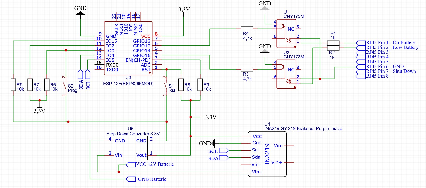
Schematic
An ESP8266-12 is used, two Optocoupler CNY17-3 for the signal “On Battery” and “Low Battery”. Additionally an INA219 breakout board to monitor the battery voltage, an DC-DC converter go get the 3.3V for the ESP8266 and some resistors and two trigger.
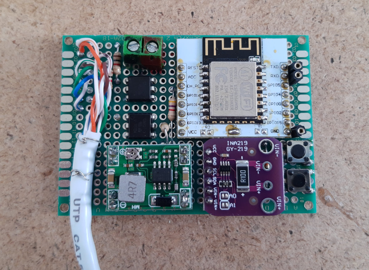
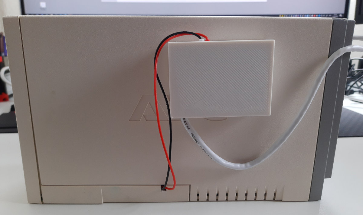
The whole packaged in a case and attached to the UPS.
Software
For the software I used Tasmota, which sends all necessary information to the network via MQTT.
First of all Download tasmota-sensors.bin and flash it to the ESP8266. For flashing you can follow the Getting Started guide.
Configuration
The module must be configured in the following way so that the UPS states can be queried.
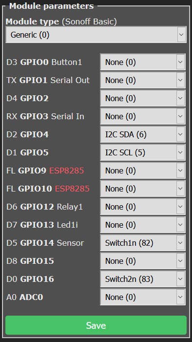
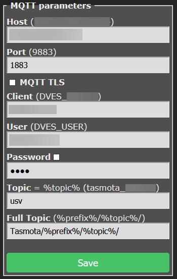
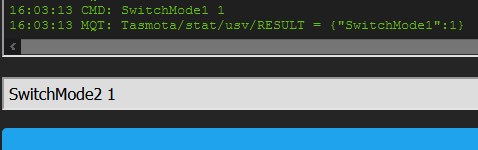
Enter the following commands in the web interface console.
Change the Voltage sensor resolution to two decimal places with VoltRes 2.
Configure the switches so that no standard MQTT messages are sent and that 0 = OFF and 1 = ON.
SwitchMode1 1
SwitchTopic1 0
SwitchMode2 1
SwitchTopic2 0
To send the status of the UPS via MQTT, a rule must be created.
Rule1
ON Switch1#state=0 DO publish Tasmota/stat/usv/OnLine %value% ENDON
ON Switch1#state=1 DO publish Tasmota/stat/usv/OnLine %value% ENDON
ON Switch1#state DO publish TelePeriod ENDON
ON Switch2#state=0 DO publish Tasmota/stat/usv/LowPower 1 ENDON
ON Switch2#state=1 DO publish Tasmota/stat/usv/LowPower 0 ENDON
ON Switch2#state DO publish TelePeriod ENDON
Additionally with TelePeriod 60 every 60 seconds a status update is sent to the topic Tasmota/stat/usv/STATE.
Now the systems which should be shut down in case of a power failure can subscribe to the topic Tasmota/stat/usv/LowBattery via MQTT and initiate a shutdown.